Showing posts with label FEM. Show all posts

Lateral torsional buckling of anisotropic laminated thin-walled simply supported beams subjected to mid-span concentrated load

H. AhmadiH.A. Rasheed


Abstract

In this paper, a generalized semi-analytical approach for lateral-torsional buckling of simply supported anisotropic, thin-walled, rectangular cross-section beams under concentrated load at mid-span/mid-height was developed using the classical laminated plate theory as a basis for the constitutive equations. A closed form buckling expression was derived in terms of the lateral, torsional and coupling stiffness coefficients of the overall composite. These coefficients were obtained through dimensional reduction by static condensation of the general 6x6 constitutive matrix mapped into an effective 2 × 2 coupled weak axis bending-twisting relationship. The resulting two coupled stability differential equations are manipulated to yield a single governing differential equation in terms of the twisting angle. This differential equation with variable coefficients, subjected to applicable boundary conditions, was solved numerically using Mathematica. The resulting solution was found to correlate with the effective lateral-flexure, torsional and coupling stiffness coefficients to yield a general semi-analytical solution. An analytical formula was possible to extract, which was verified against finite element buckling solutions using ABAQUS for a wide range of lamination orientations showing excellent accuracy. The stability of the beam under different geometric and material parameters, like length/height ratio, layer thickness, and ply orientation, was investigated

A personalized link to the article

A summary review of "Plastic Strength of Connection Elements" by Dowswell, B. (2015)

1. Abstract:

Many connection elements are modeled as rectangular members under various combinations of loads. The traditional method of combing loads using beam theory needs to be updated to fulfill the strength design philosophy due to the fact that the strength design is now used for steel members and connections. This paper has reviewed existing equations on the plastic interaction of rectangular members and has also provided new derivations where existing research is not available. Under any possible loading combination, an interaction equation is developed for strength design of rectangular connection elements.

Lateral-torsional buckling of simply supported anisotropic steel-FRP rectangular beams under pure bending condition

H.A.Rasheed, H. Ahmadi and A. Abouelleil

Abstract

In this paper, a generalized analytical approach for lateral-torsional buckling of simply supported anisotropic hybrid (steel-FRP), thin-walled, rectangular cross-section beams under pure bending condition was developed using the classical laminated plate theory as a basis for the constitutive equations. Buckling of such type of hybrid members has not been addressed in the literature. The hybrid beam, in this study, consists of a number of layers of anisotropic fiber reinforced polymer (FRP) and a layer of isotropic steel sheet. The isotropic steel sheet is used in two configurations, (i) in the mid-depth of the beam sandwiched between the different FRP layers and (ii) on the side face of the beam. A closed form buckling expression is derived in terms of the lateral, torsional and coupling stiffness coefficients of the overall composite. These coefficients are obtained through dimensional reduction by static condensation of the 6 × 6 constitutive matrix mapped into a 2 × 2 coupled weak axis bending-twisting relationship. The stability of the beam under different geometric and material parameters, like length/height ratio, ply orientation, and layer thickness, was investigated. The analytical formula is verified against finite element buckling solutions using ABAQUS for different lamination orientations showing excellent accuracy. Link to full text.

Lateral torsional buckling of anisotropic laminated composite beams subjected to various loading and boundary conditions

H. Ahmadi

Abstract

Thin-walled structures are major components in many engineering applications. When a thin-walled slender beam is subjected to lateral loads, causing moments, the beam may buckle by a combined lateral bending and twisting of cross-section, which is called lateral-torsional buckling. A generalized analytical approach for lateral-torsional buckling of anisotropic laminated, thin-walled, rectangular cross-section composite beams under various loading conditions (namely, pure bending and concentrated load) and boundary conditions (namely, simply supported and cantilever) was developed using the classical laminated plate theory (CLPT), with all considered assumptions, as a basis for the constitutive equations.
Buckling of such type of members has not been addressed in the literature. Closed form buckling expressions were derived in terms of the lateral, torsional and coupling stiffness coefficients of the overall composite. These coefficients were obtained through dimensional reduction by static condensation of the 6x6 constitutive matrix mapped into an effective 2x2 coupled weak axis bending-twisting relationship. The stability of the beam under different geometric and material parameters, like length/height ratio, ply thickness, and ply orientation, was investigated. The analytical formulas were verified against finite element buckling solutions using ABAQUS for different lamination orientations showing excellent accuracy. Link to the source.

Calculation of Stiffness Matrix for the Element Using Q4 and Q8 elements, and 3 Gauss Points

This C++  Code calculates the stiffness matrix for a given problem. It has two options: you can choose either Q4 element or Q8 element. It uses the 3 Gauss Points. The x and y coordinates for the 2D rectangular element should be inputted manually. The calculation we be given in an "output.data" file. Here is brief description of Q4 and Q8

Q4 element: 

Q4 element is a quadrilateral element that has four nodes. Its displacement field has four terms. It is called Bilinear Quadratic.

Strain Energy Methods


An alternative to statement of equilibrium equations are minimum-energy methods.

The objectives of this article is to present a brief description of concepts of strain energy methods.
The energy stored in a body due to deformation is called the "strain energy". The strain energy per unit volume is called "strain energy density" which is the area under the stress-strain curve up to the deformation point.


Work and Energy:

Consider a solid object acted upon by force, F, at a point, O, as shown in the figure. Let the deformation at the point be infinitesimal and be represented by vector dr, as shown in figure.


A simple pendulum consisting of a mass suspended in the vertical plane by a massless string.

A simple pendulum is consist of a 0.25 kg mass suspended in the vertical plane by a massless string of 0.5 m long. Assume that the pendulum moves in a plane. We need to numerically simulate the motion of the pendulum if it is released from rest with the string at 3 degrees from the vertical. We also need to plot the angle that the string makes with the vertical as a function of time. On the same axes, we need to plot the analytically solution for the angle obtained by linearizing the equations of motion assuming small oscillations.


Deriving Equations of motion:


Slider-Crank Mechanism-Case 2: A crank is being driven at a constant angular speed

Develop a simulation of response of the slider-crank mechanism shown in the picture over a period of 2 seconds. The data for the problem is as follows:
Crank length = 0.2m, crank mass = 1kg.
Connecting rod length = 0.5m, connecting rod mass = 3kg.
Slider mass = 2kg.
Spring constant = 10000 N/m, unstretched length = 0.5m.
Viscous damping coefficient = 1000 Ns/m


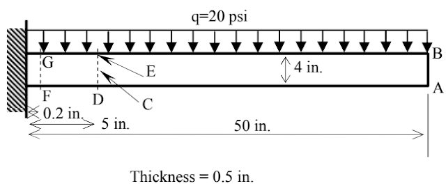
CANTILEVER BEAM WITH DISTRIBUTED LOAD

A cantilever beam has a rectangular cross section. Its left end is fixed to a rigid wall, and its top face is subjected to a distributed load q. The beam is made of plain carbon steel with Young's modulus of 30.5 Mpsi, and Poisson's ratio of 0.28. The problem is solved numerically using FEM with SolidWorks Simulation. You send an email to ask for a copy of this article.
Figure: Cantilever Beam with Distributed Load

Slider-Crank Mechanism - Case 1: Constant torque applied to the crank starting from rest


Develop a simulation of response of the slider-crank mechanism shown in the picture over a period of 2 seconds. The data for the problem is as follows:
Crank length = 0.2m, crank mass = 1kg.
Connecting rod length = 0.5m, connecting rod mass = 3kg.
Slider mass = 2kg.
Spring constant = 10000 N/m, unstretched length = 0.5m.
Viscous damping coefficient = 1000 Ns/m